Thursday, January 15, 2009

Ultra-Low Sound Air-Cooled Chillers


Air-cooled chillers provide significant advantages for many facility operators and owners. The elimination of a cooling tower greatly reduces the complexity of the system and significantly eases the maintenance of the system. For smaller facilities without the resources of large institutional owners, this reduced maintenance can be critical.

Therefore it is very common to see air-cooled chillers on smaller facilities such as public schools and small office buildings. However, this suitability does carry with it some costs--Air-cooled chillers are usually significantly less efficient than water-cooled chillers and, now with the advent of super-low sound cooling towers, often much noisier. The noise problem can be very significant with this sort of equipment in that a large proportion of the facilities that utilize this technology are located near or in residential areas.

In an earlier post I discussed how the Smardt air-cooled Turbocor chillers significantly change the balance between water-cooled and air-cooled chillers with respect to efficiency and sound. However, it is worth investigating the sound issue in more depth.

Recently, manufacturers have spent some effort in addressing the sound issue on their air-cooled chillers. This has generally been approached by providing low sound fans and addressing the compressor noise. Two products that are currently being marketed as low-sound chillers approach compressor sound in different ways. One product utilizes screw compressors with a VSD to reduce compressor sound at low loads. Another utilizes scroll compressors with elaborate compressor sound enclosures. This approach yields published sound data which is excellent at all chiller load conditions. Until recently, this chiller has been considered by many engineers to be the quietest air-cooled chiller n the market.

The Smardt chiller, of course, uses the extremely low-sound Turbocor compressor, and variable-speed ultra-low sound fans. It is reasonable to believe that this combination would make for a very favorable comparisons with these other low-sound chiller options.

And this expectation is borne out by the data. Smardt air-cooled chillers compare extremely favorably against the variable speed screw chillers as this graph illustrates:


Two things should be noted: First, the comparison here is between a 177 ton screw and a 200 ton Smardt chiller, and second that even at 100% load, the Smardt chiller is far quieter than the screw at 25% load. The difference is even more significant in the lower octave bands that carry so well over distance.

Comparing the Smardt Chiller to the acoustically treated scroll chiller also yields an extremely favorable comparison:


This comparison of 120 ton chillers shows that while both approaches yield extremely low sound levels overall, the Smardt chiller beats the competitor in 5 of 8 octave bands. And the advantage for the competitor in two of the other bands is slight. It also shows the significant effect of A-weighting sound data. In this graph, the red line represents the published sound data from the manufacturer. Close reading of this data indicates that it is not bare sound power, but A-weighted sound power. This method of reporting sound data takes very significant credits into effect, especially in the lower octave bands:

Octave band center frequency (hz) Weighting
31.5 -39
63 -26
125 -16
250 -9
500 -3
1k 0
2k 1
4k 1
8k -1


The dark blue data show the raw, uncorrected sound data for this chiller.

If acoustics are a design consideration for your air-cooled chiller product, Smardt offers a solution that is unmatched in the industry.

Extra: Audio Comparison of compressor noise

85 dBA screw compressor
73 dBA Turbocor compressor

Both measured at 1.0 m away from compressor. Your speaker volume will affect the output, but the comparison should be clear if the volume is not adjusted between clips.

Extra extra:

This link has sound files that illustrate the amplitude of a decibel, to give perspective to the graphs above.

Tuesday, January 13, 2009

EPA proposes tighter R-22 Refrigerant Regulations


In a move that could significantly affect the application of R-22 in the HVAC marketplace, the Environmental Protection Agency has proposed new rules on the Phase-out of R-22. These rules affect both the allocation of R-22 production and the installation of these products. According to an article in ACHR News:

The proposed “Adjustments to the Allowance System for Controlling HCFC Production, Import, and Export” appears to allow to EPA to go beyond the 75 percent target effective Jan. 1, 2010. The ruling also provides production allocations for various refrigerant manufacturers, ending some uncertainty in that matter.

The proposed “Ban on Sale or Distribution of Pre-Charged Appliances” says that as of Jan. 1, 2010 it will be illegal to import, produce, or sell R-22 for use in new equipment or pre-charged into such equipment. In effect, the ruling appears to say that if a contractor buys a product as of Jan. 1, 2010 that needs R-22, the charging would have to be done with existing recovered, recycled, and/or reclaimed R-22 — or R-22 alternatives — rather than virgin R-22.


These changes are significant and are detailed in depth in the AHRI summary comments of these changes.

There as a public comment period for each of these rules. EPA will accept comments until February 6, 2009 for the pre-charged rule and March 9, 2009 for the allocation rule.

Cautious owners and engineers would be wise to strongly consider making a complete switch to the HFC alternates readily available today, R-410a being the most likely option.

Monday, January 12, 2009

Tax Breaks for Ground Loop Systems

With the signing of The Emergency Economic Stabilization Act of 2008, H.R. 1424, the Federal Government has put their money where their mouth is and have acted to make geothermal heat pump systems a more attractive HVAC alternative.


Commercial geothermal heat pump installations now qualify for a 10% tax credit, with no cap on the credited expenditures!

For commercial installations, an ITC is provided for geothermal heat pumps equal to 10 percent of the expenditures, including allocable labor costs for facilities placed in service after October 3, 2008. There is no cap on the amount of expenditures which can be used for the credit (and no cap on the credit itself). In addition, geothermal heat pumps are eligible for Modified Accelerated Cost-Recovery which provides for depreciation over 5 years. The credit is determined by the cost of the system. However, if the equipment is financed by any subsidy program (federal, state or local) or with tax-exempt bond, the basis of the equipment must be reduced by the amount of the subsidy. Contrary to the residential credit, on commercial applications the units do not need to be Energy Star rated to apply. To collect this credit, the taxpayer would need to complete IRS Form 3468. The form will need revision by the IRS to reflect the addition of geothermal heat pumps.


Every little bit helps to get these highly-efficient systems to pencil out. Uncle Sam has lent a hand to owners and designers who wish to utilize this exciting technology!

Friday, December 26, 2008

Aaon Fan Engineering White Paper


Aaon has pushed the envelope of packaged rooftop unit design by providing a wide selection of fan types in their systems, including forward curved housed centrifugals, backward inclined un-housed centrifugals (plenum fans) and axial fans. And, for their larger units, they have generally moved towards direct-driven plenum fans for supply air in arrays as best fits the application. This move has not been random, but is based upon solid engineering reasoning based on the inherent stability and efficiency of these types of fans. The newly published Aaon white paper, Value in the Air provides a thorough justification for this emphasis on direct-drive plenum fans. But in doing so, it also provides an excellent primer on general fan engineering topics including overloading vs. non-overloading fan curves, fan stability in single and dual fan applications, fan control for VAV systems, and the overall energy impact of fans on our HVAC systems. It is an excellent resource and one that engineers should review to enhance their understanding of fan systems.

Wednesday, December 24, 2008

Greening Small Rooftop Units: Digital Scrolls

Digital scroll compressors offer many benefits to compressorized HVAC equipment, as I have discussed in previous articles. Some of these advantages are obvious, and need little computational support--like the modulating capacity control.

Others, however, could use some numerical support to quantify the advantages they confer. The efficiency advantage these compressors confer is one of these sorts of advantages. While it is easy to conceptually understand how this technology can improve efficiency of compressorized units, how much of an advantage this is depends on a myriad of factors, including the capacity of the unit, the operating schedule of the system, the climactic conditions the system experiences and the application of the system.

The energy advantage will change depending on whether the system operates seven days a week or five, whether the system has multiple or single compressors, whether the system is in Atlanta or Seattle, whether the system is VAV or constant volume and whether the system has hot-gas bypass or not.

Aaon realized that the complexity of this calculation made it difficult to quantify the advantage of this advanced feature. To make it easier to see the energy advantage, Aaon added a simple energy calculation tool to the Engineering Toolkit that they provide with their ECAT32 selection software.


After using the simple drop-down windows to select geographic location (by city), Aaon model number, 5 or 7 day schedule, 12 or 24 hour operation, Constant or VAV fan control you then can select the variable and constant capacity units to compare against each other. Options available include assigning hot gas bypass or not to the lead and/or lag compressors and variable speed or cycling fan control to the condenser fans. Once these options have been selected for both units, you simply hit the "calculate" button and the energy performance summary is generated.


This gives you the energy improvement conferred by the digital scroll as a percentage, and also in a comparative EER the constant capacity compressor system would have to be rated at in order for the energy performance of the two systems to be equal.

Further graphs allow you to examine the bin hours at a given OADB for the geographic location and operating schedule you specified,


and the relative energy performances of both systems at a given OADB.


A little playing around with the system allows a user to quickly find where the energy benefits are greatest. In general, the digital scroll confers the most benefit to single-compressor systems, and systems that require HGBP for constant-capacity compressors, such as VAV systems. The system also highlights the point that HGBP is a very expensive way to to capacity control, since the compressor draws full amps whenever it is running. It is the unique modulating capacity of digital scrolls that really makes a difference in these sorts of applications.

Friday, December 19, 2008

Heat your showers for FREE

Earlier in this series of articles, I discussed using the waste heat in available on-site water-based sources to heat water. Essentially, you just add a water-to-water heat pump system that allows you to move a lot of heat to a useful function with the expenditure of just a little energy.

Wouldn't it be nice if you could do this sort of transfer of heat from a waste source to a useful function without requiring the addition of a compressorized system?

Well, in existing refrigeration systems, there already exists a source of heat that is usually of a temperature that can provide useful heating for a domestic hot water application without need for additional compressors: The compressor superheat.


In a refrigeration process, where cooling is the desired function of the compressorized system, this compressor superheat is essentially waste heat, and serves no useful purpose. It is simply thrown away to the environment through whatever heat rejection process the system employs. But this compressor superheat was put into the system by the energy used to run the compressor, and therefore was paid for once by the operator of the equipment. Instead of paying for it again in the operation of the heat rejection fan or cooling tower, why not instead use it for something, saving the heat rejection costs and reaping a real benefit?

It was this sort of thinking that prompted Florida Heat Pump to develop their HRP Heat Recovery Package (pdf). This is an add-on heat exchanger that transfers the compressor superheat directly into a domestic hot-water source--using double-walled heat exchangers to protect the potable system.


The heat from the desuperheater system provides supplemental heat to the domestic hot water system any time the compressor operates--in heating or in cooling. This can greatly reduce the amount of electric or gas heat required for water heating--even completely displacing this direct heating during many times of the year, depending on the building loads and use of the space.

(Note, however, that the compressor superheat is lost to the heat pump space heating process and therefore the space heating capacity of the heat pump will be reduced by the capacity of the desuperheater. As long as this is taken into account in the sizing of the heat pump, this presents no problem to operation.)

But water-source heat pumps represent only a small part of the compressorized systems that are exisiting or installed every year. It seems there is an opportunity for taking advantage of this same heat source on many other systems and on existing equipment, too.

That is where the Heat Harvester Heat Recovery System can be used to great effect. This heat recovery system is a stand-alone desuperheating device that is pre-designed for various compressor system capacities and is available for retrofit on existing or new systems.

How much heating potential is there? Well, Heat Harvester has provided an interesting analysis of the desuperheat capacities of compressorized systems:


Size of Air Conditioning
System tons
Gallons of Hot
Water per Hour
Gallons of Hot
Water per Day
3
15-to-25
180-to-300
5
25-to-40
300-to-480
10
50-to-80
600-to-960
20
100-to-160
1200-to-1800
30
150-to-240
1800-to-2880


These systems can be economically installed into just about any compressorized systems using positive displacement compressors: Scroll and Screw air-cooled chillers, Rooftop packaged units, Condensing units, CRAC units, you name it. Since the Heat Harvester heat recovery system consists of a package with a heat exchanger and a pump, the installation basically involves a little refrigerant and water piping. And in a cooling-only application, all of the heat recovered would have otherwise been lost to the environment.

Wednesday, December 3, 2008

Ultimate Florida Heat Pump Cheat Sheet


One of the difficulties our customers have with Florida Heat Pump is that their product offering is so wide, that it can sometimes get confusing: Which models have ECM motors? Which have scroll compressors and which have recip? What sound packages are available for a given model, etc...

So, in the interest of clarity and ease of use, we've pulled together all of this information into one convenient place: The Ultimate Florida Heat Pump Cheat Sheet

Tuesday, November 4, 2008

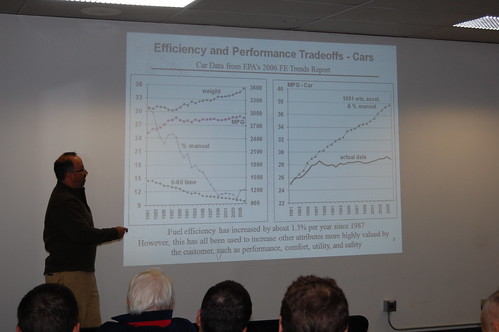
Presentations from JB 2008 Open House

Due to a slew of interest, we have made the following presentation slides available for review.


All of the links below go to pdf files of the presentation, except for the Aggressive Building Energy Performance presentation which goes to the NBI website where similar presentations can be found.

Click on the underlined words to link to the documents.

Thanks again for your interest and your participation!

More photos from the event can be found here.

Monday, November 3, 2008

Energy Code and Relief air in Rooftop Units

In a warm building served by rooftop units in a cold ambient condition, air wants to do an unfortunate thing. Warm, less dense air tends to rise through the colder, denser air. If unchecked, this causes an air migration up through the ductwork, to the RTU and out into the environment, while cold air is infiltrated into the building to make up the vacated volume. This causes a loss of heating energy detrimental to the energy performance of the building.


If the rooftop unit is operating, this stack effect is usually more than overcome by the pressures developed by the fans. But when the unit is off, often the only thing preventing warm air from working its way up through the ductwork is the action of the unit dampers. Most units installed under the Seattle Energy code have an automatic OA damper associated with the economizer that can be driven closed. But the relief air path is a different story. Often, this air path is controlled with a simple gravity damper configured to relieve air when the building is under positive pressure, but to prevent air from entering while under negative pressure.

The problem with this arrangement is that it does nothing to prevent a stack effect from occurring when the unit is not operating. The damper will act to let warm air out, which is exactly what is what we would hope to avoid. To address thisl, the 2006 Seattle Energy code has a section that requires a positive-closing damper on all air openings on building air systems:

1412.4.1 Dampers: Outside air intakes, exhaust outlets and relief outlets serving conditioned spaces shall be equipped with motorized dampers which close automatically when the system is off or upon power failure. Stair shaft and elevator shaft smoke relief openings shall be equipped with normally open (fails open upon loss of power) dampers. These dampers shall remain closed until activated by the fire alarm system or other approved smoke detection system.

EXCEPTIONS:

  1. Systems serving areas which require continuous operation.
  2. Combustion air intakes.
  3. Gravity (non-motorized) dampers are acceptable in systems with a design outdoor air intake or exhaust capacity of 300 cfm or less buildings less than 3 stories in height.
  4. Gravity (non-motorized dampers are acceptable in exhaust and relief outlets in the first story and levels below the first story of buildings three or more stories in height. Reserved
  5. Type 1 grease hoods exhaust.

Dampers installed to comply with this section, including dampers integral to HVAC equipment, shall have a maximum leakage rate when tested in accordance with AMCA Standard 500 of:

  1. Motorized dampers: 10 cfm/ft2 of damper area at 1.0 in. w.g.
  2. Non-motorized dampers: 20 cfm/ft2 of damper area at 1.0 in. w.g., except that for non-motorized dampers smaller than 24 inches in either dimension: 40 cfm/ft2 of damper area at 1.0 in. w.g.

Dampers used as a component of packaged HVAC equipment shall comply with the damper leakage requirements, unless it is the lowest leakage available as a factory option. Drawings shall indicate compliance with this section.


This has caused some disruption in the rootop packaged unit market, because the option of providing automatically closing motorized dampers on all air openings on these sorts of units is not one that is easily available from most manufacturers.

Johnson-Barrow has worked with Aaon to provide an engineered option on most configurations of the Aaon RM and RN rooftop packaged line to meet this requirement.

So if you have a project where a packaged RTU is the right solution, there is a code-compliant option likely available from Aaon.

Tuesday, October 7, 2008

Open House: Where, When and How

THURSDAY, OCTOBER 16th!


Details:


Where: 2001 22nd Ave S, Seattle WA, 10:00 AM to 6:00 PM

The open house will be located just down the street from the JB offices, about 5 blocks south of I-90, just off of Rainier Avenue in Seattle.

(click for active map, or click HERE)


Directions: Directions from your location can be found by clicking on on the active map above, then right-clicking on the open house location, selecting "Directions to" and typing in your starting address in the box provided! Parking is available.

Transit: Plan your trip Here (Use "2001 22nd Ave S" as the destination)

What:


Schedule of Presentations:

  • 10:30 AM: Non-Chemical Water Treatment Case Studies. John Junk, Fluid-Tek
  • 12:30 PM: Aggressive Building Energy Performance: Getting to 50 and Beyond. Mark Frankel, New Buildings Institute
  • 1:45 PM: PSE/SCL Energy incentive updates
  • 2:30 PM: Introduction to Variable-Refrigerant Flow Systems. Kim Olson, Sanyo
  • 3:30 PM: Introduction to Active Chilled Beams. Rand Conger, Johnson-Barrow
Lunch provided at 11:30 AM to 1:30 PM

Refreshments provided 4:00 PM to 6:00 PM


Featured Products on site for your inpsection:

Climate Craft Matrix Air Handler

Evapco AT cooling tower with Super Low Sound Fan

Evapco Pulse~Pure non-chemical water treatment

Sanyo Mini-Splits

Dadanco Active Chilled Beams

Cerus Starters

And even MORE!

How:

Come throughout the day. Visit for as long or as short as you like

If you do plan to come, we would appreciate some feedback on when you think you will be here.

Please visit HERE to give us a quick RSVP. Thanks! (We'll still let you in if you don't)